ACPR measurements on G4BAO’s 2.5W 23cm LDMOS driver amplifier
PE1GTA, 31 Jan 2016
During the recent X-mas break I had access to an Agilent/Keysight EXG IQ vector signal generator and made some DVB-S spectral re-growth measurements on G4BAO’s 23 cm driver amplifier. I was curious to see what the ST PD85004 LDMOS device was capable of, mostly for my own DATV experiments and came away pleasantly surprised.
The measurement setup consisted of the aforementioned EXG signal generator driving the amplifier under test and my trusted HP8566B spectrum analyzer capturing the output signal after a precision 10dB attenuator on the amplifier (to protect the SA’s input attenuator). The sig gen was configured to generate a 4Msymbol/s PRBS RRC (root raised cosine) filtered (α=0.35) QPSK signal at 1260 MHz with output power levels stepped from 0dBm to 20dBm in 5 dB steps. The measurement cables (incl. adapters) to and from the amplifier had a loss of 1.7dB each.
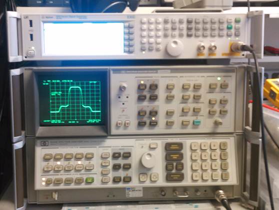
Fig. 1. Agilent EXG sig gen and
HP8566B spectrum analyzer.
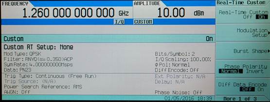
Fig. 2 EXG modulation settings.
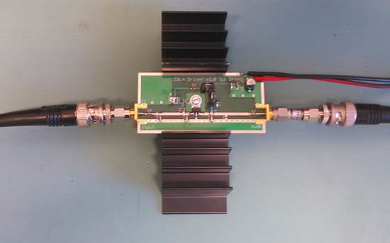
Fig.3. Amplifier under test on heat-sink (PCB version 1.0, C12
not mounted).
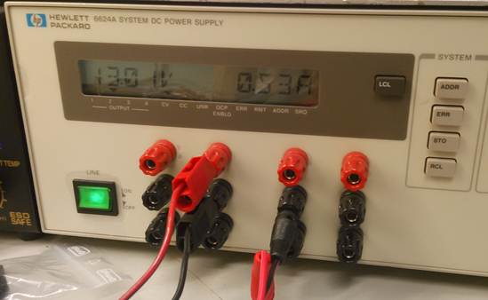
Fig.4. The amplifier under test was
biased in class A with Vdrain=13V and Idqs=0.53A.
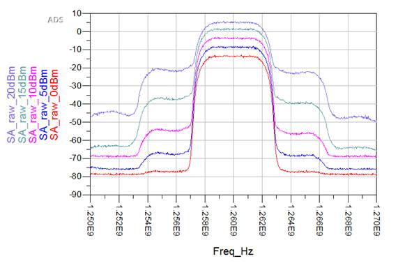
Fig.5. Spectrum as captured for 5 different input power levels.
SA settings: RBW=100kHz, VBW=300Hz, 1001 points, Sweep_time=2s, normal detection.
To my knowledge there is no channel spacing defined for DVB-S signals, so we can’t really speak of ACPR (Adjacent Channel Power Ratio). To come up with a quantitative measure for spectral regrowth, I calculated the power ratio from a 1 MHz of ‘first-shoulder’ (3rd order intermod) spectrum and a 1 MHz of in-band spectrum.
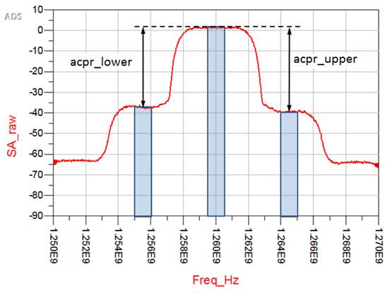
Fig. 6. ACPR is calculated as a
ratio of the power in a 1 MHz section in the first 'shoulder' and a 1 MHz
section in the main spectrum.
The amplifier output power itself is calculated by integrating the power of the main spectrum over (1+α)*SR (=5.4 MHz), taking into account losses and (video) averaging of logarithmically displayed noise [1].
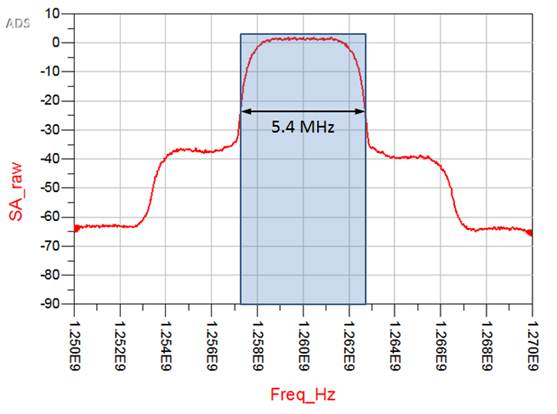
Fig.7. Amplifier output power is calculated from the
integrated power in a 5.4 MHz band around the center frequency.
|
Pgen [dBm] |
Pin [dBm] |
Pout [dBm] |
ACPR lower [dBc] |
ACPR upper [dBc] |
Gain [dB] |
|
0 |
-1.7 |
15.3 |
-63.8 |
-63.7 |
17.0 |
|
5 |
3.3 |
20.3 |
-59.9 |
-59 |
17.0 |
|
10 |
8.3 |
25.3 |
-52.6 |
-50.9 |
17.0 |
|
15 |
13.3 |
30.2 |
-40.8 |
-38.6 |
16.9 |
|
20 |
18.3 |
33.9 |
-27.9 |
-26.6 |
15.6 |
Table.1. Calculated 'ACPR' for the first lower and upper intermodulation
shoulders.
Not bad at all; 1 Watt of DVB-S with spectrum regrowth around -40dBc.
References:
1. Agilent Technologies, "Measuring Noise and Noise-like Digital Communications
Signals with Spectrum and Signal Analyzers"
http://cp.literature.agilent.com/litweb/pdf/5966-4008E.pdf